# TinyML - Motion Recognition Using Raspberry Pi Pico
 This tutorial has two parts. The first is to explore the Raspberry Pi Pico, its main components, and how to program it using Micropython and its C/C++ SDK (Software Development Kit). Next, we will use the Pico to capture "gesture data" on a TinyML model training using Edge Impulse Studio. Once developed and tested, the model will be deployed for real inference on the same device. Here is a quick view of the final project:
> If you are familiar with Pico's basic programming, please feel are to jump for part 2, where the real fun will begin!
## PART 1: Exploring the Raspberry Pi Pico and its SDK
### The Raspberry Pi Pico
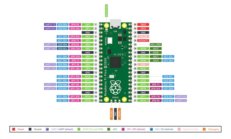
Raspberry Pi Pico is a low-cost, high-performance microcontroller board with flexible digital interfaces. Key features include:
* RP2040 microcontroller chip designed by Raspberry Pi Foundation
* Dual-core Arm Cortex M0+ processor, flexible clock running up to 133 MHz
* 264KB of SRAM and 2MB of onboard Flash memory
* USB 1.1 with device and host support
* Low-power sleep and dormant modes
* 26 × multi-function GPIO pins
* 2 × SPI, 2 × I2C, 2 × UART, 3 × 12-bit ADC, 16 × controllable PWM channels
* Accurate clock and timer on-chip
* Temperature sensor
* Accelerated floating-point libraries on-chip
* 8 × Programmable I/O (PIO) state machines for custom peripheral support
This tutorial has two parts. The first is to explore the Raspberry Pi Pico, its main components, and how to program it using Micropython and its C/C++ SDK (Software Development Kit). Next, we will use the Pico to capture "gesture data" on a TinyML model training using Edge Impulse Studio. Once developed and tested, the model will be deployed for real inference on the same device. Here is a quick view of the final project:
> If you are familiar with Pico's basic programming, please feel are to jump for part 2, where the real fun will begin!
## PART 1: Exploring the Raspberry Pi Pico and its SDK
### The Raspberry Pi Pico
Raspberry Pi Pico is a low-cost, high-performance microcontroller board with flexible digital interfaces. Key features include:
* RP2040 microcontroller chip designed by Raspberry Pi Foundation
* Dual-core Arm Cortex M0+ processor, flexible clock running up to 133 MHz
* 264KB of SRAM and 2MB of onboard Flash memory
* USB 1.1 with device and host support
* Low-power sleep and dormant modes
* 26 × multi-function GPIO pins
* 2 × SPI, 2 × I2C, 2 × UART, 3 × 12-bit ADC, 16 × controllable PWM channels
* Accurate clock and timer on-chip
* Temperature sensor
* Accelerated floating-point libraries on-chip
* 8 × Programmable I/O (PIO) state machines for custom peripheral support
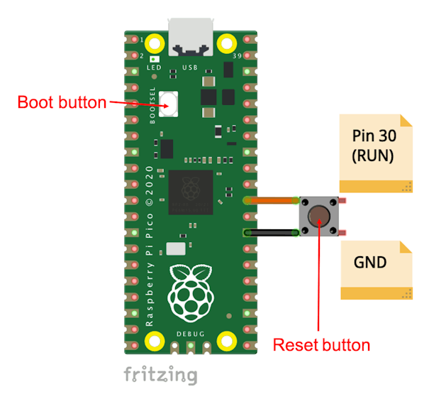
 > An interesting characteristic is its ability to drag-and-drop programming using mass storage over USB.
Despite that, it is straightforward to "upload" a program to the Pico; what is missing is a reset push-button to prevent USB disconnection every time a new code is uploaded, which can damage the Pico USB connector. Fortunately, pin 30 (RUN) can be used for this function. Use a push-button (normally open) to connect this pin to the ground. Now, anytime a program should be uploaded to Pico, press both buttons simultaneously.
> An interesting characteristic is its ability to drag-and-drop programming using mass storage over USB.
Despite that, it is straightforward to "upload" a program to the Pico; what is missing is a reset push-button to prevent USB disconnection every time a new code is uploaded, which can damage the Pico USB connector. Fortunately, pin 30 (RUN) can be used for this function. Use a push-button (normally open) to connect this pin to the ground. Now, anytime a program should be uploaded to Pico, press both buttons simultaneously.
 In this documentation link, it is possible to find detailed information about the [MCU RP 2040](https://datasheets.raspberrypi.org/rp2040/rp2040-datasheet.pdf), the heart of Pico.
### Programming the Pico
There are two ways of programming a Pico: MicroPython and C/C++.Programming using MicroPythonFor initial tests (and for beginners), running MicroPython with the Pico is extremely easy. Once the Pico is plugged for the first time into your computer (via USB) and with the BOOT button pressed (or pressing Reset and Boot after connection), a window named RPI-RP2 should appear as a typical Mass Storage Device (same as a regular Pen-Driver).
In this documentation link, it is possible to find detailed information about the [MCU RP 2040](https://datasheets.raspberrypi.org/rp2040/rp2040-datasheet.pdf), the heart of Pico.
### Programming the Pico
There are two ways of programming a Pico: MicroPython and C/C++.Programming using MicroPythonFor initial tests (and for beginners), running MicroPython with the Pico is extremely easy. Once the Pico is plugged for the first time into your computer (via USB) and with the BOOT button pressed (or pressing Reset and Boot after connection), a window named RPI-RP2 should appear as a typical Mass Storage Device (same as a regular Pen-Driver).
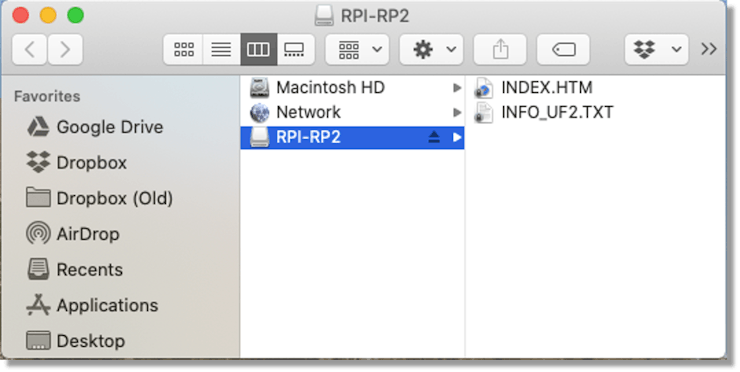 Clicking on [INDEX.HTM ](https://www.raspberrypi.org/documentation/rp2040/getting-started/#rp2040-boards)will send you to a page where you can start with MicroPython.
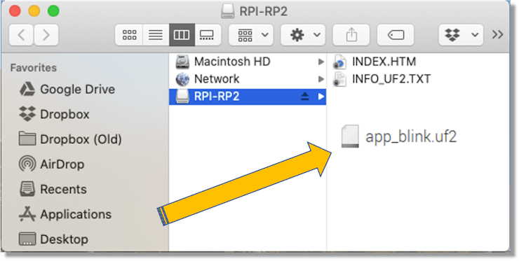
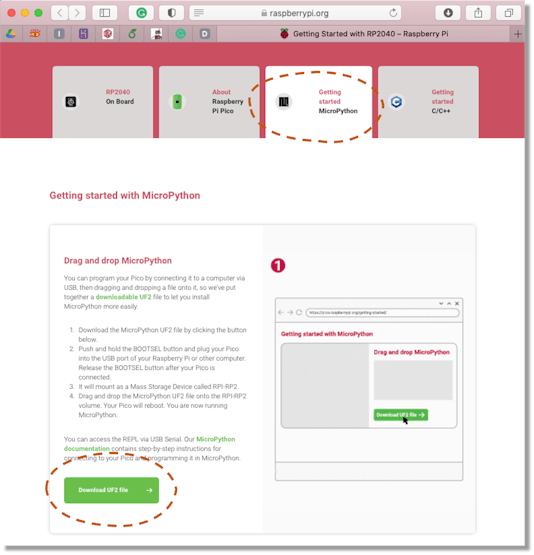 Follow the instructions to download the UF2 file to easily install the MicroPython interpreter in the Pico. Having the UF2 file, only drag it to that RPI-RP2 window, and that is it! The Pico is ready to receive an executable Python script. For MicroPython, I suggest [Thonny ](https://thonny.org/)as the IDE of choice once it is possible to write Python scripts directly on the shell as below or develop a script on the editor:
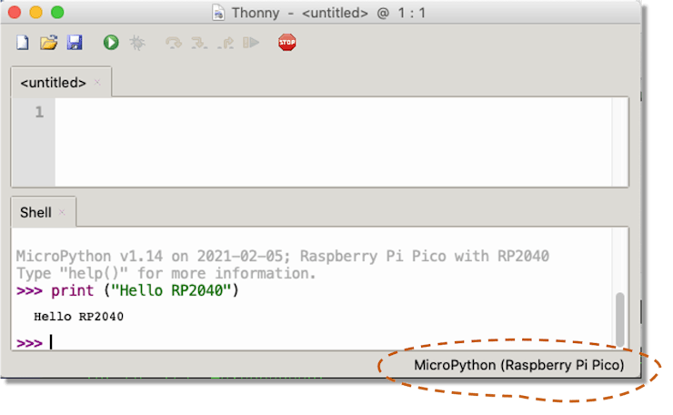 > Confirm that the interpreter is configured to the Pico. Clic on it (IDE Inferior right corner) for options.
It is also possible to write or enter with Python scripts, as the blink example below:
> Confirm that the interpreter is configured to the Pico. Clic on it (IDE Inferior right corner) for options.
It is also possible to write or enter with Python scripts, as the blink example below:
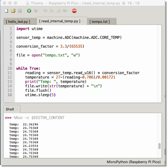
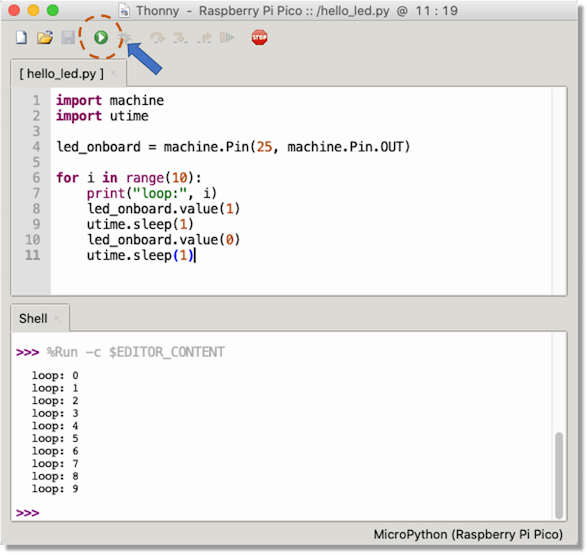 The script is uploaded to the Pico with the Run button (marked in the above figure). The internal LED (pin 25) will flash ten times, printing the loop number on the Shell. Try to read the internal temperature sensor now, creating a log file to monitor internal Pico temp. In this example, the temp.txt log file is stored inside the Pico, so pay attention to how much memory space you need.
 If you are new to MicroPython, the Raspberry Pi Foundation put together an excellent book, [Get Started with MicroPython on Raspberry Pi Pico ](https://hackspace.raspberrypi.org/books/micropython-pico)(free in pdf), that will teach all the steps on physical computing using the Pico e MicroPython. MicroPython programming is suitable for initial exploration and learning electronics, but using C/C++ language for real embedded projects is crucial. For that, it is necessary to understand the SDK C/C++.The RPi Foundation put together excellent documentation. The first one, [Getting Started with the Raspberry Pi Pico g](https://rptl.io/pico-get-started)ives information on how to set up your hardware, IDE/environment, and how to build and debug software for the Raspberry Pi Pico (and other RP2040-based devices). The second document, [Raspberry Pi Pico C/C++ SDK, explores ](https://rptl.io/pico-c-sdk)programming using the SDK with advanced features and gives complete API documentation.
### SDK installation with Linux:
Install tools (Cmake and gcc for ARM):
```
sudo apt update
sudo apt install git cmake gcc-arm-none-eabi libnewlib-arm-none-eabi build-essential
```
Create a folder where the projects will be developed:
```
cd ~/
mkdir pico
cd pico
```
Clone the SDK repository:
```
git clone -b master https://github.com/raspberrypi/pico-sdk.git
```
Go to the pico-sdk folder and update sub-modules:
```
cd pico-sdk
git submodule update --init
```
Return to pico folder
```
cd ..
```
### SDK installation with MacOS
Install Toolkit
```
brew install cmake
brew tap ArmMbed/homebrew-formulae
brew install arm-none-eabi-gcc
```
Install the SDK
```
cd ~/
mkdir pico
cd pico
git clone -b master https://github.com/raspberrypi/pico-sdk.git
cd pico-sdk
git submodule update --init
cd ..
```
At this point, you are all set to create an embedded project using C/C++
### Creating a Blink Project in C/C++
It's good to download the examples created specifically for Pico. They will give us a good starting point to handle the HW and libraries.
```
git clone -b master https://github.com/raspberrypi/pico-examples.git
```
The examples also have a blink code, but let's start a complete one from scratch.First, create a folder where your project will be located (under /pico/ and at the same level as your /pico-sdk is located:
```
cd~/
cd pico
mkdir blink
cd blink
mkdir build
```
Note that we also create a sub-folder named build. This folder will receive the final compiled code to be uploaded to Pico.In the project folder (in this case, blink), we always must have 3 files:
* blink.c (the main C code)
* [CMakeList.txt](http://cmakelist.txt/) (that tells the SDK how to turn the C file into a binary application for an RP2040-based microcontroller board)
* pico\_sdk\_import.cmake (help to locate the SDK)
Let's start to copy pico\_sdk\_import.cmake in the folder project:
```
cp ../pico-sdk/external/pico_sdk_import.cmake .
```
> For blink.c (C source file) and CMakeList.txt, use a text editor that you like more, like as Sublime, Eclipse, VS, Geany.
Let's see the CMakeList.txt:
```
cmake_minimum_required(VERSION 3.12)
project(app_blink_project)
include(pico_sdk_import.cmake)
pico_sdk_init()
add_executable(app_blink
blink.c
)
pico_add_extra_outputs(app_blink)
target_link_libraries(app_blink pico_stdlib)
```
Note that we will create an executable file named app\_blink based on the code of blink.c. Now, the source code blink.c:
```
/**
* Pico - RP2040
* Blink Internal LED
*/
#include "pico/stdlib.h"
const uint LED_PIN = 25;
int main() {
gpio_init(LED_PIN);
gpio_set_dir(LED_PIN, GPIO_OUT);
gpio_put(LED_PIN, 0);
while (true) {
gpio_put(LED_PIN, 1);
sleep_ms(250);
gpio_put(LED_PIN, 0);
sleep_ms(250);
}
}
```
At the top of the C file, we include a header called pico/stdlib.h. This is an umbrella header that pulls in some other commonly used headers. The ones needed here are hardware/gpio.h, which is used for accessing the general-purpose IOs on RP2040 (the gpio\_xxx functions here), and pico/time.h, which contains, among other things, the sleep\_msfunction.A library whose name starts with pico provides high-level APIs and concepts or aggregates smaller interfaces; a name beginning with hardware indicates a thinner abstraction between your code and RP2040 on-chip hardware. So, using mainly the hardware\_gpio and pico\_time libraries, this C program will blink an LED connected to GPIO25 on and off twice per second, forever (or at least until unplugged). Great! At this point, your project folder should contain three files and one sub-folder (build):
```
pico/
├── blink/
│ ├── blink.c
│ ├── CMakeLists.txt
│ ├── pico_sdk_import.cmake
│ └── build/
│
├── pico-sdk/
│ ├── cmake
│ └── external
│ └── ...
```
Now, go to the build folder, export the environment variables, and run cmake:
```
cd build
export PICO_SDK_PATH=../../pico-sdk
cmake ..
```
The last step is to compile the project:
```
make -j4
```
In the build folder, several files are generated, including the app\_build.uf2, the executable file. Press Boot and Reset to open the window RPI-RP2 and drag the compiled project file app\_build.uf2 to that folder.
If you are new to MicroPython, the Raspberry Pi Foundation put together an excellent book, [Get Started with MicroPython on Raspberry Pi Pico ](https://hackspace.raspberrypi.org/books/micropython-pico)(free in pdf), that will teach all the steps on physical computing using the Pico e MicroPython. MicroPython programming is suitable for initial exploration and learning electronics, but using C/C++ language for real embedded projects is crucial. For that, it is necessary to understand the SDK C/C++.The RPi Foundation put together excellent documentation. The first one, [Getting Started with the Raspberry Pi Pico g](https://rptl.io/pico-get-started)ives information on how to set up your hardware, IDE/environment, and how to build and debug software for the Raspberry Pi Pico (and other RP2040-based devices). The second document, [Raspberry Pi Pico C/C++ SDK, explores ](https://rptl.io/pico-c-sdk)programming using the SDK with advanced features and gives complete API documentation.
### SDK installation with Linux:
Install tools (Cmake and gcc for ARM):
```
sudo apt update
sudo apt install git cmake gcc-arm-none-eabi libnewlib-arm-none-eabi build-essential
```
Create a folder where the projects will be developed:
```
cd ~/
mkdir pico
cd pico
```
Clone the SDK repository:
```
git clone -b master https://github.com/raspberrypi/pico-sdk.git
```
Go to the pico-sdk folder and update sub-modules:
```
cd pico-sdk
git submodule update --init
```
Return to pico folder
```
cd ..
```
### SDK installation with MacOS
Install Toolkit
```
brew install cmake
brew tap ArmMbed/homebrew-formulae
brew install arm-none-eabi-gcc
```
Install the SDK
```
cd ~/
mkdir pico
cd pico
git clone -b master https://github.com/raspberrypi/pico-sdk.git
cd pico-sdk
git submodule update --init
cd ..
```
At this point, you are all set to create an embedded project using C/C++
### Creating a Blink Project in C/C++
It's good to download the examples created specifically for Pico. They will give us a good starting point to handle the HW and libraries.
```
git clone -b master https://github.com/raspberrypi/pico-examples.git
```
The examples also have a blink code, but let's start a complete one from scratch.First, create a folder where your project will be located (under /pico/ and at the same level as your /pico-sdk is located:
```
cd~/
cd pico
mkdir blink
cd blink
mkdir build
```
Note that we also create a sub-folder named build. This folder will receive the final compiled code to be uploaded to Pico.In the project folder (in this case, blink), we always must have 3 files:
* blink.c (the main C code)
* [CMakeList.txt](http://cmakelist.txt/) (that tells the SDK how to turn the C file into a binary application for an RP2040-based microcontroller board)
* pico\_sdk\_import.cmake (help to locate the SDK)
Let's start to copy pico\_sdk\_import.cmake in the folder project:
```
cp ../pico-sdk/external/pico_sdk_import.cmake .
```
> For blink.c (C source file) and CMakeList.txt, use a text editor that you like more, like as Sublime, Eclipse, VS, Geany.
Let's see the CMakeList.txt:
```
cmake_minimum_required(VERSION 3.12)
project(app_blink_project)
include(pico_sdk_import.cmake)
pico_sdk_init()
add_executable(app_blink
blink.c
)
pico_add_extra_outputs(app_blink)
target_link_libraries(app_blink pico_stdlib)
```
Note that we will create an executable file named app\_blink based on the code of blink.c. Now, the source code blink.c:
```
/**
* Pico - RP2040
* Blink Internal LED
*/
#include "pico/stdlib.h"
const uint LED_PIN = 25;
int main() {
gpio_init(LED_PIN);
gpio_set_dir(LED_PIN, GPIO_OUT);
gpio_put(LED_PIN, 0);
while (true) {
gpio_put(LED_PIN, 1);
sleep_ms(250);
gpio_put(LED_PIN, 0);
sleep_ms(250);
}
}
```
At the top of the C file, we include a header called pico/stdlib.h. This is an umbrella header that pulls in some other commonly used headers. The ones needed here are hardware/gpio.h, which is used for accessing the general-purpose IOs on RP2040 (the gpio\_xxx functions here), and pico/time.h, which contains, among other things, the sleep\_msfunction.A library whose name starts with pico provides high-level APIs and concepts or aggregates smaller interfaces; a name beginning with hardware indicates a thinner abstraction between your code and RP2040 on-chip hardware. So, using mainly the hardware\_gpio and pico\_time libraries, this C program will blink an LED connected to GPIO25 on and off twice per second, forever (or at least until unplugged). Great! At this point, your project folder should contain three files and one sub-folder (build):
```
pico/
├── blink/
│ ├── blink.c
│ ├── CMakeLists.txt
│ ├── pico_sdk_import.cmake
│ └── build/
│
├── pico-sdk/
│ ├── cmake
│ └── external
│ └── ...
```
Now, go to the build folder, export the environment variables, and run cmake:
```
cd build
export PICO_SDK_PATH=../../pico-sdk
cmake ..
```
The last step is to compile the project:
```
make -j4
```
In the build folder, several files are generated, including the app\_build.uf2, the executable file. Press Boot and Reset to open the window RPI-RP2 and drag the compiled project file app\_build.uf2 to that folder.
 > You can also use cp at command line, instead of dragging the file.
For example, on a Mac:
```
cp app_blink.uf2 /Volumes/RPI-RP2
```
And, on an RPi:
```
cp app_blink.uf2 /media/pi/RPI-RP2
```
Despite that, all those steps seem complicated; once your project environment is set up, for any changes in the project, you should only compile the new code using make or make -j4 (That uses all four cores of the CPU).
## PART 2: TinyML - Motion Recognition Project using the Pico
The idea of this project is to use the Pico to classify some human-made gestures as "up-down, " "left-right," and "circle". This classification will be done 100% "off-line" at the MPU level. In other words, we will do "embedded machine learning, also known as TinyML.
> As explained on Edge Impulse documentation ([What is embedded ML, anyway?](https://docs.edgeimpulse.com/docs/what-is-embedded-machine-learning-anyway)), recent advances in microprocessor architecture and algorithm design have made it possible to run sophisticated machine learning workloads on even the smallest microcontrollers (our case with RP2040).
Depending on HW capacity and memory size, different types of MCU/Applications can be used in the TinyML arena, as shown in the below chart.
> You can also use cp at command line, instead of dragging the file.
For example, on a Mac:
```
cp app_blink.uf2 /Volumes/RPI-RP2
```
And, on an RPi:
```
cp app_blink.uf2 /media/pi/RPI-RP2
```
Despite that, all those steps seem complicated; once your project environment is set up, for any changes in the project, you should only compile the new code using make or make -j4 (That uses all four cores of the CPU).
## PART 2: TinyML - Motion Recognition Project using the Pico
The idea of this project is to use the Pico to classify some human-made gestures as "up-down, " "left-right," and "circle". This classification will be done 100% "off-line" at the MPU level. In other words, we will do "embedded machine learning, also known as TinyML.
> As explained on Edge Impulse documentation ([What is embedded ML, anyway?](https://docs.edgeimpulse.com/docs/what-is-embedded-machine-learning-anyway)), recent advances in microprocessor architecture and algorithm design have made it possible to run sophisticated machine learning workloads on even the smallest microcontrollers (our case with RP2040).
Depending on HW capacity and memory size, different types of MCU/Applications can be used in the TinyML arena, as shown in the below chart.
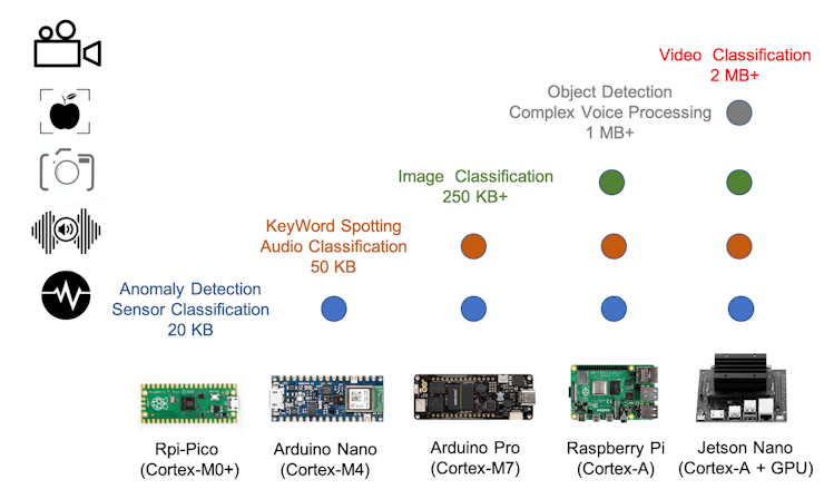 > Our Pico, based on ARM Cortex-M0+ is more than suitable to perform Sensor Classification, as we will do in this project.
### The Machine Learning Workflow
So far, we have already defined the 1st phase of the project: its goal (Gesture Classification). The below workflow shows all the remaining phases to be executed from data collection on our Pico till the final inference and evaluation back to our tiny device, passing for the real model development done at Edge Impulse Studio in the cloud.
> Our Pico, based on ARM Cortex-M0+ is more than suitable to perform Sensor Classification, as we will do in this project.
### The Machine Learning Workflow
So far, we have already defined the 1st phase of the project: its goal (Gesture Classification). The below workflow shows all the remaining phases to be executed from data collection on our Pico till the final inference and evaluation back to our tiny device, passing for the real model development done at Edge Impulse Studio in the cloud.
 ### Collect a dataset
TinyML enables machine intelligence right next to the physical world using sensors. So, the first thing to do is to capture data to understand those gestures. For that, we will use a simple 3-axis accelerometer. The SensorThe sensor used, the [MMA7361L ](https://www.itead.cc/wiki/MMA7361L_Module)is a three-axis analog accelerometer that requires a meager amount of power and has a g-select input, which switches the accelerometer between ±1.5g and ±6g measurement ranges. Other features include a sleep mode, signal conditioning, a 1-pole low pass filter, temperature compensation, self-test, and 0g-detect, which detects linear freefall. Zero-g offset and sensitivity are factory-set and require no external devices.
### Collect a dataset
TinyML enables machine intelligence right next to the physical world using sensors. So, the first thing to do is to capture data to understand those gestures. For that, we will use a simple 3-axis accelerometer. The SensorThe sensor used, the [MMA7361L ](https://www.itead.cc/wiki/MMA7361L_Module)is a three-axis analog accelerometer that requires a meager amount of power and has a g-select input, which switches the accelerometer between ±1.5g and ±6g measurement ranges. Other features include a sleep mode, signal conditioning, a 1-pole low pass filter, temperature compensation, self-test, and 0g-detect, which detects linear freefall. Zero-g offset and sensitivity are factory-set and require no external devices.
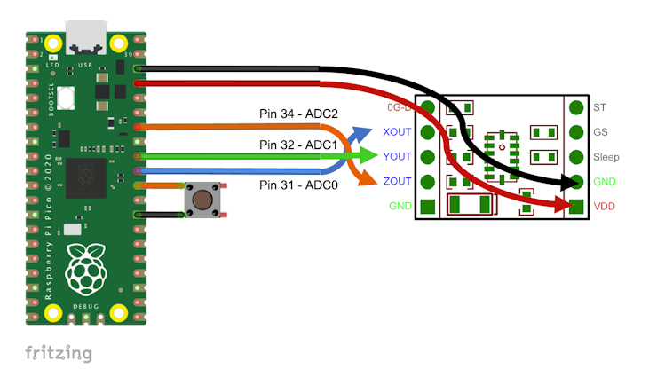
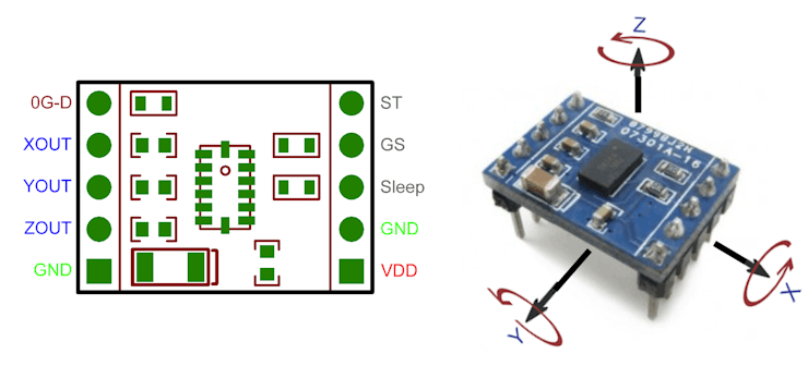 Each sensor analog output (XOUT, YOUT, and ZOUT) will be connected to Pico's ADC inputs (ADC0, 1, and 2). The VDD is 3.3V and will also be supplied by Pico. The pin GS selected the g-level and will be left open (+/-1.5G).Wiring
 > There are several different packages for three-axis analog accelerometer. In principle any breakout board for Freescale's MMA7361L should work.
Sensor Measurements: With the pin GS left open (+/-1.5G), the sensor sensibility according to spec is 800mV/g, being that for 1G (sensor resting), the output is around 1.65V ('G0'). It is important to remember that Pico ADCs have a resolution of 12bits (3.3V ==> 4096), so if we want the ADC measurement in g, we must apply the following conversion factor to raw data collected (read\_axis\_raw):
```
conversion_factor = 3.3V / 4096
read_axis_in_g = (read_axis_raw * conversion_factor) - G0
```
And for acceleration in m/s:
```
CONVERT_G_TO_MS2 = 9.80665
read_axis_in_ms = read_axis_in_g * CONVERT_G_TO_MS2
```
### Preparing the project environment.
The Data Collection project file tree structure should be:
```
pico/
├── accelerometer_data_capture/
│ ├── accel_mma7361l.c
│ ├── CMakeLists.txt
│ ├── pico_sdk_import.cmake
│ └── build/
│
├── pico-sdk/
│ ├── cmake
│ └── external
│ └── ...
```
Below is the source code for data collection:
```
#include
#include "pico/stdlib.h"
#include "hardware/gpio.h"
#include "hardware/adc.h"
#include "pico/binary_info.h"
#define NSAMP 10
#define G0 1.65f
#define CONVERT_G_TO_MS2 9.80665f
#define FREQUENCY_HZ 50
#define INTERVAL_MS (1000 / (FREQUENCY_HZ + 1))
const float conversion_factor = 3.3f / (1 << 12);
float get_axis (int adc_n) {
adc_select_input(adc_n);
unsigned int axis_raw = 0;
for (int i=0;i
> There are several different packages for three-axis analog accelerometer. In principle any breakout board for Freescale's MMA7361L should work.
Sensor Measurements: With the pin GS left open (+/-1.5G), the sensor sensibility according to spec is 800mV/g, being that for 1G (sensor resting), the output is around 1.65V ('G0'). It is important to remember that Pico ADCs have a resolution of 12bits (3.3V ==> 4096), so if we want the ADC measurement in g, we must apply the following conversion factor to raw data collected (read\_axis\_raw):
```
conversion_factor = 3.3V / 4096
read_axis_in_g = (read_axis_raw * conversion_factor) - G0
```
And for acceleration in m/s:
```
CONVERT_G_TO_MS2 = 9.80665
read_axis_in_ms = read_axis_in_g * CONVERT_G_TO_MS2
```
### Preparing the project environment.
The Data Collection project file tree structure should be:
```
pico/
├── accelerometer_data_capture/
│ ├── accel_mma7361l.c
│ ├── CMakeLists.txt
│ ├── pico_sdk_import.cmake
│ └── build/
│
├── pico-sdk/
│ ├── cmake
│ └── external
│ └── ...
```
Below is the source code for data collection:
```
#include
#include "pico/stdlib.h"
#include "hardware/gpio.h"
#include "hardware/adc.h"
#include "pico/binary_info.h"
#define NSAMP 10
#define G0 1.65f
#define CONVERT_G_TO_MS2 9.80665f
#define FREQUENCY_HZ 50
#define INTERVAL_MS (1000 / (FREQUENCY_HZ + 1))
const float conversion_factor = 3.3f / (1 << 12);
float get_axis (int adc_n) {
adc_select_input(adc_n);
unsigned int axis_raw = 0;
for (int i=0;i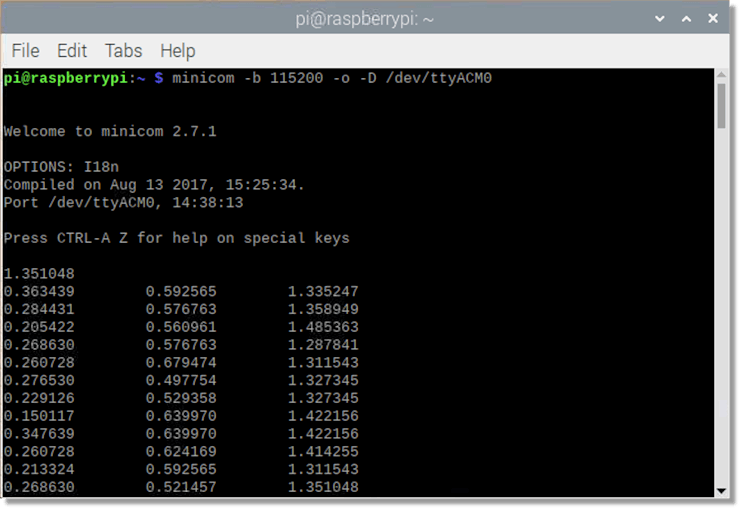 One alternative is the program Serial or even the Arduino IDE Serial Monitor and Plotter on macOS.
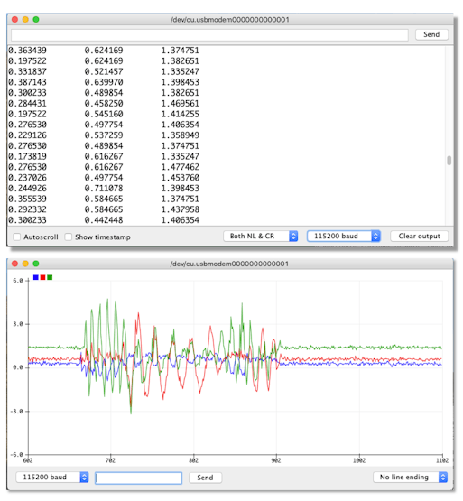 > Alternatively, the code on [15\_pico\_accel\_multicore\_capture\_data,](https://github.com/Mjrovai/Pico-Motion-Recognition/tree/main/15_pico_accel_multicore_capture_data) shows how to capture data continuosly on Core 1, when the data is sent to Serial by the code running on Core 0.
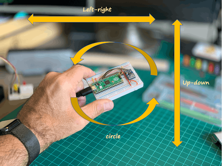
What we need to do now is to collect data samples (set of 3-axis values) for each one of the human-made gestures that we want to classify:
* "up-down" (Moving the Pico/Sensor from a high position to a lower)
* "left-right" (Moving the Pico/Sensor from left to right and vice-versa)
* "circle". (Moving the Pico/Sensor in circles CW and CCW).
* "resting" (Left the Pico/Sensor on the table, with no movement)
> Alternatively, the code on [15\_pico\_accel\_multicore\_capture\_data,](https://github.com/Mjrovai/Pico-Motion-Recognition/tree/main/15_pico_accel_multicore_capture_data) shows how to capture data continuosly on Core 1, when the data is sent to Serial by the code running on Core 0.
What we need to do now is to collect data samples (set of 3-axis values) for each one of the human-made gestures that we want to classify:
* "up-down" (Moving the Pico/Sensor from a high position to a lower)
* "left-right" (Moving the Pico/Sensor from left to right and vice-versa)
* "circle". (Moving the Pico/Sensor in circles CW and CCW).
* "resting" (Left the Pico/Sensor on the table, with no movement)
 > If you do not have an account at [Edge Impulse Studio](https://www.edgeimpulse.com/), do it now! Edge Impulse is the leading development platform for machine learning on edge devices, free for developers and trusted by enterprises. Open an account and create a new project.
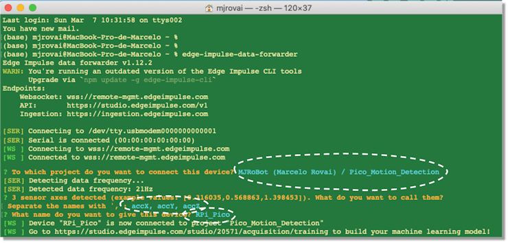
My project is public and can be cloned here: [Pico\_Motion\_Detection.](https://studio.edgeimpulse.com/public/20571/latest)Once you have created your project, install Edge Impulse CLI on your computer; follow these instructions: [CLI Installation.](https://docs.edgeimpulse.com/docs/cli-installation) This should be done only one time.Once the project is created and the CLI is installed, the easiest way of getting data from Pico is using the Edge Impulse [Data forwarder. T](https://docs.edgeimpulse.com/docs/cli-data-forwarder)his lets you forward data collected over a serial interface to the studio. This method only works perfectly on sensors with lower sampling frequencies, as in our case (human gestures).The data forwarder is used to easily relay data from any device to Edge Impulse over serial (exactly our case). Devices write sensor values over a serial connection, and the data forwarder collects the data, signs the data, and sends the data to the ingestion service.At your terminal, run:
```
edge-impulse-data-forwarder
```
The CLI will ask for your credentials, the name of the project that you are working on, and the name of the data values that we will capture (note that the CLI already analyzed the serial and knows that the 3-axis sensor data are available) and finally will ask you for a device name (optional).
> If you do not have an account at [Edge Impulse Studio](https://www.edgeimpulse.com/), do it now! Edge Impulse is the leading development platform for machine learning on edge devices, free for developers and trusted by enterprises. Open an account and create a new project.
My project is public and can be cloned here: [Pico\_Motion\_Detection.](https://studio.edgeimpulse.com/public/20571/latest)Once you have created your project, install Edge Impulse CLI on your computer; follow these instructions: [CLI Installation.](https://docs.edgeimpulse.com/docs/cli-installation) This should be done only one time.Once the project is created and the CLI is installed, the easiest way of getting data from Pico is using the Edge Impulse [Data forwarder. T](https://docs.edgeimpulse.com/docs/cli-data-forwarder)his lets you forward data collected over a serial interface to the studio. This method only works perfectly on sensors with lower sampling frequencies, as in our case (human gestures).The data forwarder is used to easily relay data from any device to Edge Impulse over serial (exactly our case). Devices write sensor values over a serial connection, and the data forwarder collects the data, signs the data, and sends the data to the ingestion service.At your terminal, run:
```
edge-impulse-data-forwarder
```
The CLI will ask for your credentials, the name of the project that you are working on, and the name of the data values that we will capture (note that the CLI already analyzed the serial and knows that the 3-axis sensor data are available) and finally will ask you for a device name (optional).
 Return to Edge Impulse Studio and go to the Data Acquisition section:
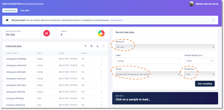 Your device name, the available sensor, and the capture frequency should appear automatically. Define the data label and the amount of sample you want (default is 10s), and press Start Sample. Below are 10 seconds of the up\_down gesture.
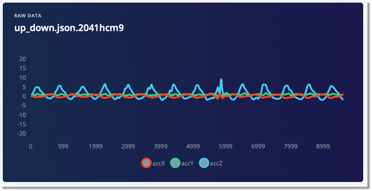 > Note that accZ (blue line) has the highest pics, what make sense.
"Machine Learning is a way of writing programs that process raw data and turn it into meaningful information at an application level". Hence, the more data you have, the more information you can get! Let's capture at least 60 seconds of data for each label. Try to balance your dataset, having the exact data for each label (class).
### Feature Engineering
Now, we have all the raw data needed for training. But as you saw with the last image, raw data is a time series type of data, and it is not easy to create a model that understands such kind of data. So, the data should be pre-processed. For that, we will take a window of 2 seconds and extract some relevant values from that, for example, the RMS value for such a group of data and its main frequency components (FFT). From each window, 33 features will be generated (11 per axis).
> Note that accZ (blue line) has the highest pics, what make sense.
"Machine Learning is a way of writing programs that process raw data and turn it into meaningful information at an application level". Hence, the more data you have, the more information you can get! Let's capture at least 60 seconds of data for each label. Try to balance your dataset, having the exact data for each label (class).
### Feature Engineering
Now, we have all the raw data needed for training. But as you saw with the last image, raw data is a time series type of data, and it is not easy to create a model that understands such kind of data. So, the data should be pre-processed. For that, we will take a window of 2 seconds and extract some relevant values from that, for example, the RMS value for such a group of data and its main frequency components (FFT). From each window, 33 features will be generated (11 per axis).
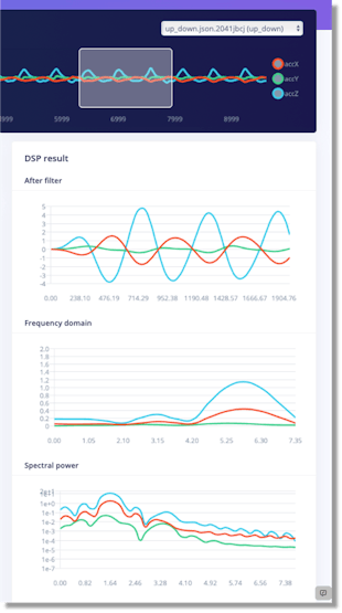 It could seem complex, but the good news is that Edge Impulse will do this almost automatically for us. Feature Engineering and Model Definition (Impulse Design)Let's go back a little. Once you have your raw data, go to the Impulse Design section and create your project impulse.
> An impulse takes raw data, uses signal processing to extract features, and then uses a learning block to classify new data.
It could seem complex, but the good news is that Edge Impulse will do this almost automatically for us. Feature Engineering and Model Definition (Impulse Design)Let's go back a little. Once you have your raw data, go to the Impulse Design section and create your project impulse.
> An impulse takes raw data, uses signal processing to extract features, and then uses a learning block to classify new data.
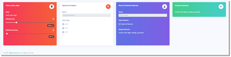 In short, the Impulse will split the raw data into 2-second segments. But note that those windows will slide over time, with 80ms of displacement. With this, more data will be generated.In the Spectral Features section, the general parameters for the feature generation can be defined. I stayed with default values, and on the Generate features tab, it was possible to explore visually all 3,879 samples generated.
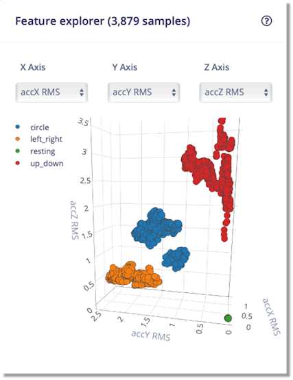 Our dataset classes are very well-defined, suggesting our classification model should work fine.
> Note that orange data (left-right) goes manly on the y-axis, and that red data (up-down) goes along the z-axis. Also, resting (green dot) shows no acceleration, which is expected (on the previous stage, the earth acceleration (g) was filtered from the z-axis.
### Design and Train the Neural Networks (NN) Classifier
The NN Classifier model can be straightforward:
Our dataset classes are very well-defined, suggesting our classification model should work fine.
> Note that orange data (left-right) goes manly on the y-axis, and that red data (up-down) goes along the z-axis. Also, resting (green dot) shows no acceleration, which is expected (on the previous stage, the earth acceleration (g) was filtered from the z-axis.
### Design and Train the Neural Networks (NN) Classifier
The NN Classifier model can be straightforward:
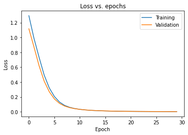
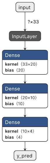 The model has 33 neurons in its first layer (1 neuron for each feature) and four neurons in the last layer (1 neuron for each of the four classes). The model has two hidden layers with 20 and 10 neurons. The default hyper-parameters are 30 epochs (a lot and can be reduced in half in this case) and a learning rate 0.0005. Running the training, we ended with an accuracy of 100%, confirmed by the F1 Score. This is not normal with Deep Learning projects, but we realized that the data classes were very well split. Only 80% of data was used for training during the training phase, with 20% spare for validation. Both sets of data performed well, and it does not seem that the model overfitted, as shown in the Loss vs. Epoch graph:
 Here is the Edge Impulse Studio Training result:
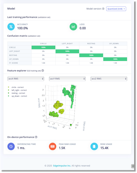 > This quantized model is expected to take around 1ms in inference time, using 1.5Kb in RAM and 15.4Kb in ROM. Very good!
Testing the model with real (new) dataIn the Studio Live Classification Section, you can repeat what was done during the data capture phase. Once I kept the same type of movements, the result was excellent.
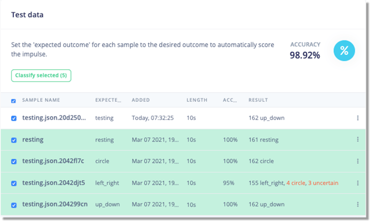
> All data captured in this section are stored as Test Data, analyzed in Data Acquisition Section, under the tab Test Data.
The next phase tests the model with entirely new data (stored in the Data Acquisition/Test Data section). The result was excellent again, only with some confusion mixing left\_right with the circle, which is expected.
> This quantized model is expected to take around 1ms in inference time, using 1.5Kb in RAM and 15.4Kb in ROM. Very good!
Testing the model with real (new) dataIn the Studio Live Classification Section, you can repeat what was done during the data capture phase. Once I kept the same type of movements, the result was excellent.
> All data captured in this section are stored as Test Data, analyzed in Data Acquisition Section, under the tab Test Data.
The next phase tests the model with entirely new data (stored in the Data Acquisition/Test Data section). The result was excellent again, only with some confusion mixing left\_right with the circle, which is expected.
 ### Conversion & Deployment
Once the model is developed, trained, and tested, the next step in our Machine Learning Workflow is Conversion and Deployment. On the Edge Impulse Deployment section, deploying both the trained model and the pre-processing block (Signal Processing) as a C++ library is possible.
> For MCUs that work with Arduino IDE, the studio automatically generates the libraries and workable examples that can be used as starting point for real inference.
In Raspberry Pi Pico's case, we will choose the C++ Library option once this MCU does not work yet with Arduino IDE. But, we will still use one of Arduino's code examples as our starting point. Also, we will enable the [Edge Optimized Neural (EON™) Compiler,](https://www.edgeimpulse.com/blog/introducing-eon) which permits to run of neural networks in 25-55% less RAM, and up to 35% less flash while retaining the same accuracy compared to TensorFlow Lite for Microcontrollers, as we can see below:
### Conversion & Deployment
Once the model is developed, trained, and tested, the next step in our Machine Learning Workflow is Conversion and Deployment. On the Edge Impulse Deployment section, deploying both the trained model and the pre-processing block (Signal Processing) as a C++ library is possible.
> For MCUs that work with Arduino IDE, the studio automatically generates the libraries and workable examples that can be used as starting point for real inference.
In Raspberry Pi Pico's case, we will choose the C++ Library option once this MCU does not work yet with Arduino IDE. But, we will still use one of Arduino's code examples as our starting point. Also, we will enable the [Edge Optimized Neural (EON™) Compiler,](https://www.edgeimpulse.com/blog/introducing-eon) which permits to run of neural networks in 25-55% less RAM, and up to 35% less flash while retaining the same accuracy compared to TensorFlow Lite for Microcontrollers, as we can see below:
 Pressing the BUILD button on this studio section will download the complete package for our final project.
### Inference
Now, it is time to do machine learning on embedding devices! We will program our Pico to recognize the gestures entirely offline, without an internet connection. This is the revolution that TinyML is doing!
### Preparing the project environment
The C/C++ package downloaded from Edge Impulse Studio has the following folders/files:
```
├── edge-impulse-sdk/
├── model-parameters/
├── tflite-model/
├── CMakeLists.txt
```
We will update the CMakeLists.txt with the needed specific information for our project and add our C++ source code (that will be under a source folder). The Gesture Recognition Collection project file tree structure should be:
```
pico/
├── pico_gesture_recognition_inference/
│ ├── edge-impulse-sdk/
│ ├── model-parameters/
│ ├── tflite-model/
│ ├── source/
│ ├── CMakeLists.txt
│ ├── pico_sdk_import.cmake
│ └── build/
│
├── pico-sdk/
│ ├── cmake
│ └── external
│ └── ...
```
Based on the excellent tutorial [Machine Learning Inference on Raspberry Pico 2040 ](https://www.hackster.io/dmitrywat/machine-learning-inference-on-raspberry-pico-2040-e6e874)by [Dmitry Maslov,](https://www.hackster.io/dmitrywat) which inspired me on this project, we could create the [CMakeLists.txt](http://cmakelists.txt/) below. The final executable program will be named "app":
```
cmake_minimum_required(VERSION 3.13)
set(MODEL_FOLDER .)
set(EI_SDK_FOLDER edge-impulse-sdk)
include(pico_sdk_import.cmake)
project(pico_motion_detection_project C CXX ASM)
set(CMAKE_C_STANDARD 11)
set(CMAKE_CXX_STANDARD 17)
pico_sdk_init()
add_executable(app
source/main.cpp
source/ei_classifier_porting.cpp
)
include(${MODEL_FOLDER}/edge-impulse-sdk/cmake/utils.cmake)
pico_enable_stdio_usb(app 1)
target_link_libraries(app pico_stdlib hardware_adc)
add_subdirectory(${MODEL_FOLDER}/edge-impulse-sdk/cmake/zephyr)
target_include_directories(app PRIVATE
${MODEL_FOLDER}
${MODEL_FOLDER}/classifer
${MODEL_FOLDER}/tflite-model
${MODEL_FOLDER}/model-parameters
)
target_include_directories(app PRIVATE
${EI_SDK_FOLDER}
${EI_SDK_FOLDER}/third_party/ruy
${EI_SDK_FOLDER}/third_party/gemmlowp
${EI_SDK_FOLDER}/third_party/flatbuffers/include
${EI_SDK_FOLDER}/third_party
${EI_SDK_FOLDER}/tensorflow
${EI_SDK_FOLDER}/dsp
${EI_SDK_FOLDER}/classifier
${EI_SDK_FOLDER}/anomaly
${EI_SDK_FOLDER}/CMSIS/NN/Include
${EI_SDK_FOLDER}/CMSIS/DSP/PrivateInclude
${EI_SDK_FOLDER}/CMSIS/DSP/Include
${EI_SDK_FOLDER}/CMSIS/Core/Include
)
include_directories(${INCLUDES})
# find model source files
RECURSIVE_FIND_FILE(MODEL_FILES "${MODEL_FOLDER}/tflite-model" "*.cpp")
RECURSIVE_FIND_FILE(SOURCE_FILES "${EI_SDK_FOLDER}" "*.cpp")
RECURSIVE_FIND_FILE(CC_FILES "${EI_SDK_FOLDER}" "*.cc")
RECURSIVE_FIND_FILE(S_FILES "${EI_SDK_FOLDER}" "*.s")
RECURSIVE_FIND_FILE(C_FILES "${EI_SDK_FOLDER}" "*.c")
list(APPEND SOURCE_FILES ${S_FILES})
list(APPEND SOURCE_FILES ${C_FILES})
list(APPEND SOURCE_FILES ${CC_FILES})
list(APPEND SOURCE_FILES ${MODEL_FILES})
# add all sources to the project
target_sources(app PRIVATE ${SOURCE_FILES})
pico_add_extra_outputs(app)
```
Taking as starting point the Arduino example: nano\_ble33\_sense\_accelerometer.ino and changing the instructions that are not compatible, create the file main.cpp below. The internal LED will flash during the time that the data is captured and classified:
```
/* Includes ---------------------------------------------------------------- */
#include
#include "pico/stdlib.h"
#include "ei_run_classifier.h"
#include "hardware/gpio.h"
#include "hardware/adc.h"
/* Constant defines -------------------------------------------------------- */
#define CONVERT_G_TO_MS2 9.80665f
#define G0 1.65f
#define NSAMP 10
/* Private variables ------------------------------------------------------- */
static bool debug_nn = false; // Set this to true to see e.g. features generated from the raw signal
const float conversion_factor = 3.3f / (1 << 12);
const uint LED_PIN = 25;
float readAxisAccelation (int adc_n) {
adc_select_input(adc_n);
unsigned int axis_raw = 0;
for (int i=0;i
Pressing the BUILD button on this studio section will download the complete package for our final project.
### Inference
Now, it is time to do machine learning on embedding devices! We will program our Pico to recognize the gestures entirely offline, without an internet connection. This is the revolution that TinyML is doing!
### Preparing the project environment
The C/C++ package downloaded from Edge Impulse Studio has the following folders/files:
```
├── edge-impulse-sdk/
├── model-parameters/
├── tflite-model/
├── CMakeLists.txt
```
We will update the CMakeLists.txt with the needed specific information for our project and add our C++ source code (that will be under a source folder). The Gesture Recognition Collection project file tree structure should be:
```
pico/
├── pico_gesture_recognition_inference/
│ ├── edge-impulse-sdk/
│ ├── model-parameters/
│ ├── tflite-model/
│ ├── source/
│ ├── CMakeLists.txt
│ ├── pico_sdk_import.cmake
│ └── build/
│
├── pico-sdk/
│ ├── cmake
│ └── external
│ └── ...
```
Based on the excellent tutorial [Machine Learning Inference on Raspberry Pico 2040 ](https://www.hackster.io/dmitrywat/machine-learning-inference-on-raspberry-pico-2040-e6e874)by [Dmitry Maslov,](https://www.hackster.io/dmitrywat) which inspired me on this project, we could create the [CMakeLists.txt](http://cmakelists.txt/) below. The final executable program will be named "app":
```
cmake_minimum_required(VERSION 3.13)
set(MODEL_FOLDER .)
set(EI_SDK_FOLDER edge-impulse-sdk)
include(pico_sdk_import.cmake)
project(pico_motion_detection_project C CXX ASM)
set(CMAKE_C_STANDARD 11)
set(CMAKE_CXX_STANDARD 17)
pico_sdk_init()
add_executable(app
source/main.cpp
source/ei_classifier_porting.cpp
)
include(${MODEL_FOLDER}/edge-impulse-sdk/cmake/utils.cmake)
pico_enable_stdio_usb(app 1)
target_link_libraries(app pico_stdlib hardware_adc)
add_subdirectory(${MODEL_FOLDER}/edge-impulse-sdk/cmake/zephyr)
target_include_directories(app PRIVATE
${MODEL_FOLDER}
${MODEL_FOLDER}/classifer
${MODEL_FOLDER}/tflite-model
${MODEL_FOLDER}/model-parameters
)
target_include_directories(app PRIVATE
${EI_SDK_FOLDER}
${EI_SDK_FOLDER}/third_party/ruy
${EI_SDK_FOLDER}/third_party/gemmlowp
${EI_SDK_FOLDER}/third_party/flatbuffers/include
${EI_SDK_FOLDER}/third_party
${EI_SDK_FOLDER}/tensorflow
${EI_SDK_FOLDER}/dsp
${EI_SDK_FOLDER}/classifier
${EI_SDK_FOLDER}/anomaly
${EI_SDK_FOLDER}/CMSIS/NN/Include
${EI_SDK_FOLDER}/CMSIS/DSP/PrivateInclude
${EI_SDK_FOLDER}/CMSIS/DSP/Include
${EI_SDK_FOLDER}/CMSIS/Core/Include
)
include_directories(${INCLUDES})
# find model source files
RECURSIVE_FIND_FILE(MODEL_FILES "${MODEL_FOLDER}/tflite-model" "*.cpp")
RECURSIVE_FIND_FILE(SOURCE_FILES "${EI_SDK_FOLDER}" "*.cpp")
RECURSIVE_FIND_FILE(CC_FILES "${EI_SDK_FOLDER}" "*.cc")
RECURSIVE_FIND_FILE(S_FILES "${EI_SDK_FOLDER}" "*.s")
RECURSIVE_FIND_FILE(C_FILES "${EI_SDK_FOLDER}" "*.c")
list(APPEND SOURCE_FILES ${S_FILES})
list(APPEND SOURCE_FILES ${C_FILES})
list(APPEND SOURCE_FILES ${CC_FILES})
list(APPEND SOURCE_FILES ${MODEL_FILES})
# add all sources to the project
target_sources(app PRIVATE ${SOURCE_FILES})
pico_add_extra_outputs(app)
```
Taking as starting point the Arduino example: nano\_ble33\_sense\_accelerometer.ino and changing the instructions that are not compatible, create the file main.cpp below. The internal LED will flash during the time that the data is captured and classified:
```
/* Includes ---------------------------------------------------------------- */
#include
#include "pico/stdlib.h"
#include "ei_run_classifier.h"
#include "hardware/gpio.h"
#include "hardware/adc.h"
/* Constant defines -------------------------------------------------------- */
#define CONVERT_G_TO_MS2 9.80665f
#define G0 1.65f
#define NSAMP 10
/* Private variables ------------------------------------------------------- */
static bool debug_nn = false; // Set this to true to see e.g. features generated from the raw signal
const float conversion_factor = 3.3f / (1 << 12);
const uint LED_PIN = 25;
float readAxisAccelation (int adc_n) {
adc_select_input(adc_n);
unsigned int axis_raw = 0;
for (int i=0;i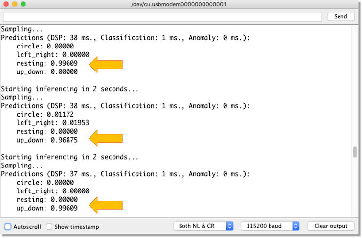 > Note that Classification time (Inference) is 1ms, same as predict by Edge Impulse Studio.
#### Final Considerations
The next step in this project would be to detect anomalies, which is also simple to implement with Edge Impulse Studio. For those curious about TinyML, I strongly suggest the Coursera free course [Introduction to Embedded Machine Learning | Edge Impulse.](https://coursera.org/learn/introduction-to-embedded-machine-learning) Here is a glimpse of one of the projects that I developed during the course, classification operation modes and anomalies on a Blender:
> Note that Classification time (Inference) is 1ms, same as predict by Edge Impulse Studio.
#### Final Considerations
The next step in this project would be to detect anomalies, which is also simple to implement with Edge Impulse Studio. For those curious about TinyML, I strongly suggest the Coursera free course [Introduction to Embedded Machine Learning | Edge Impulse.](https://coursera.org/learn/introduction-to-embedded-machine-learning) Here is a glimpse of one of the projects that I developed during the course, classification operation modes and anomalies on a Blender:
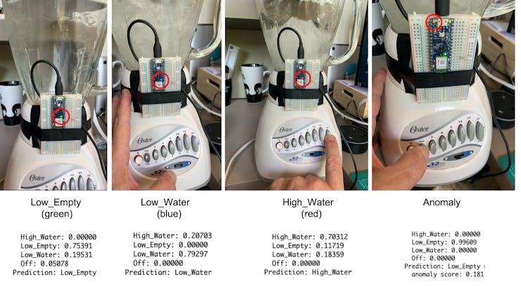 You can also clone this project on Edge Impulse Studio: [Blender - Motion Detection](https://studio.edgeimpulse.com/studio/17968).
#### Conclusion
This project's general idea was to learn how to program a Raspberry Pi Pico and do a proof of concept that is possible to perform Machine Learning with this MCU, which, at the time that I wrote the tutorial, was not officially supported by Edge Impulse and Arduino. Today, both Arduino and EI support the Pico, which simplifies the coding process for non-expert developers enormously. On my GitHub repository, you will find the last version of the codes: [Pico-Motion-Recognition.](https://github.com/Mjrovai/Pico-Motion-Recognition)
---
# Agent Instructions: Querying This Documentation
If you need additional information that is not directly available in this page, you can query the documentation dynamically by asking a question.
Perform an HTTP GET request on the current page URL with the `ask` query parameter:
```
GET https://tinyml4d.gitbook.io/edge-machine-learning/motion/tinyml-motion-recognition-using-raspberry-pi-pico.md?ask=
```
The question should be specific, self-contained, and written in natural language.
The response will contain a direct answer to the question and relevant excerpts and sources from the documentation.
Use this mechanism when the answer is not explicitly present in the current page, you need clarification or additional context, or you want to retrieve related documentation sections.
You can also clone this project on Edge Impulse Studio: [Blender - Motion Detection](https://studio.edgeimpulse.com/studio/17968).
#### Conclusion
This project's general idea was to learn how to program a Raspberry Pi Pico and do a proof of concept that is possible to perform Machine Learning with this MCU, which, at the time that I wrote the tutorial, was not officially supported by Edge Impulse and Arduino. Today, both Arduino and EI support the Pico, which simplifies the coding process for non-expert developers enormously. On my GitHub repository, you will find the last version of the codes: [Pico-Motion-Recognition.](https://github.com/Mjrovai/Pico-Motion-Recognition)
---
# Agent Instructions: Querying This Documentation
If you need additional information that is not directly available in this page, you can query the documentation dynamically by asking a question.
Perform an HTTP GET request on the current page URL with the `ask` query parameter:
```
GET https://tinyml4d.gitbook.io/edge-machine-learning/motion/tinyml-motion-recognition-using-raspberry-pi-pico.md?ask=
```
The question should be specific, self-contained, and written in natural language.
The response will contain a direct answer to the question and relevant excerpts and sources from the documentation.
Use this mechanism when the answer is not explicitly present in the current page, you need clarification or additional context, or you want to retrieve related documentation sections.